Chapter IX
Floating Drydocks
Advance Base Sectional Dock No. 3The fleet of floating drydocks built by the Bureau of Yards and Docks during World War II was a significant and at times dramatic factor in the Navy's success in waging global war.
It had long been recognized that in the event of another world war the fleet would be required to operate in remote waters, and that ships were going to suffer hard usage and serious battle damage. It was obvious that many crippled ships would be lost, or at least would be out of action for months while returning to home ports for repairs, unless mobile floating drydocks could be provided that could trail the fleet wherever it went. It was the Bureau's responsibility to meet these requirements.
Floating drydocks have been used for overhaul and repair of ships for many years, and many ingenious designs have been devised from time to time. One of the most interesting was the Adamson dock, patented in 1816, which may be considered the prototype of some of the new mobile docks. The Navy apparently built several wooden sectional docks at various navy yards about 1850, but little is known of their history.
About 1900, two new steel floating drydocks were built for the Navy. The first of these, of 18,000 tons lifting capacity, was built in 1899-1902 at Sparrow's Point, Md., and towed to the Naval Station a Algiers, La., where it was kept in intermittent service for many years. In 1940, it was towed via the Panama Canal to Pearl Harbor to supplement the inadequate docking facilities there. Since the dock was wider than the Canal locks, it was necessary to disassemble it at Cristobal and to reassemble it at Balboa. Although both the dock and the ship in it were damaged during the Japanese attack on Pearl Harbor on December 7, 1941, the dock was not lost, but was quickly repaired and subsequently performed invaluable service both in the salvaging of vessels damaged in that attack and in the support of the fleet in the Pacific.
The other dock, the Dewey, was a 16,000-ton dock, built in three sections, and capable of docking itself. It was constructed in 1903-1905, also at Sparrow's Point, Md., and was towed via the Suez Canal to the Philippines. The saga of this voyage is an epic of ocean towing history. The Dewey was still in service at Olongapo when the Japanese invaded the Philippines early in 1942. [sic: Preliminary landings took place as early as 8 December, with the main landings following on the 21st. Manila was occupied on New Years Day. -- HyperWar] It was scuttled by the American naval forces before they abandoned the station.
Neither of these docks was suitable for mobile operation. Between 1920 and 1930, the Bureau of Yards and Docks made numerous studies of various types of mobile docks of both unit and sectional types. In 1933, funds were finally obtained for one 2,200-ton dock, and the Bureau designed and built the ARD-1. This dock was of revolutionary design. It was a one-piece dock, ship-shaped in form, with a molded closed bow and a faired stern, and may be best described as U-shaped in both plan and cross-section. The stern was closed by a bottom-hinged flap gate, operated by hydraulic rams. This gate was lowered to permit entrance of a ship into the submerged dock and then closed. The dock was then raised by pumping water from the ballast compartments and also from the main basin. This dock was equipped with its own diesel-electric power plant, pumping plant, repair shops, and crew's accommodations. It was the first drydock in any navy which was sufficiently self-sustaining to accompany a fleet into remote waters.
The ARD-1 was towed to Pearl Harbor, where it was used successfully throughout the war. Thirty docks of this type, somewhat larger and incorporating many improvements adopted as a result of operational experience with this experimental dock, were constructed and deployed throughout the world during the war.
In 1935, the Bureau obtained $10,000,000 for a
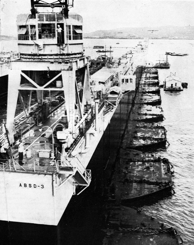
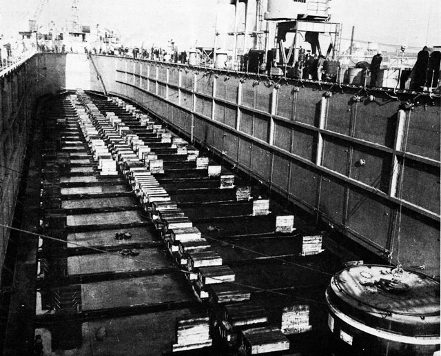
Advance Base Sectional Dock in the South Pacific
View shows keel blocks and bilge blocks set to accommodate a ship.similar one-piece mobile dock, to be capable of lifting any naval vessel afloat. Complete plans and specifications were prepared by the Bureau for this dock, which was to be 1,027 feet long, 165 feet beam, and 75 feet molded depth. Bids received for this huge drydock, designed as the ARD-3, appreciably exceeded the appropriation, and the project was abandoned when the additional funds needed for its execution were refused.
At the same time, plans were prepared for the ARD-2, an improved and enlarged model of the ARD-1. It was not until November 1940, however, that funds were obtained for its construction, and the project placed under contract. The ARD-2, and an additional dock, the ARD-5, were completed in the spring of 1942. Additional docks of this type were built in rapid succession and were delivered during 1943 and 1944 at an average rate of more than one a month.
The war program of floating drydocks included a wide variety of types to meet the varying service requirements for which they were designed. The principal categories were as follows: Types of Floating Drydocks
- ABSD -- Advance Base Sectional Dock.
- Mobile, military, steel dock, either (a) of ten sections of 10,000 tons lifting capacity each, or (b) of seven sections of 8,000 tons lifting capacity, for battleships, carriers, cruisers, and large auxiliaries.
- ARD -- Auxiliary Repair Dock.
- Mobile, military, steel unit dock, ship-form hull, with a normal lifting capacity of 3,500 tons, for destroyers, submarines, and small auxiliaries.
- ARDC -- Auxiliary Repair Dock, Concrete.
- Mobile, military concrete trough type, unit dock with faired bow and stern, 2,800 tons lifting capacity.
- AFD -- Auxiliary Floating Dock.
- Mobile, military, steel trough type, unit dock, with faired bow and stern, of 1,000 tons lifting capacity.
- AFDL -- Auxiliary Floating Dock, Lengthened.
- Mobile, steel trough type, unit dock, similar to AFD's, but lengthened and enlarged to provide 1,900 tons lifting capacity.
- YFD -- Yard Floating Dock.
- This category included a wide variety of types, designed generally for yard or harbor use, with services supplied from shore. Among the principal types were 400-ton concrete trough docks; 1,000-ton, 3,000-ton and 5,000-ton one-piece timber trough docks; sectional timber docks ranging from 7,000 to 20,000 tons lifting capacity; and three-piece self-docking steel sectional docks of 14,000 to 18,000 tons lifting capacity.
These classifications were modified in 1946 in order to make the standard nomenclature of floating drydocks consistent and more descriptive. Four class designations were established, as follows:
- AFDB -- Auxiliary Floating Drydock Big.
- 30,000 tons and larger.
- AFDM -- Auxiliary Floating Drydock Medium.
- 10,000 to 30,000 tons.
- AFDL -- Auxiliary Floating Drydock Little.
- Less than 10,000 tons.
- AFDL(C) -- Auxiliary Floating Drydock Little (Concrete).
Under this modification, the ABSD's were redesignated AFDB's; the ARD's became AFDU's; the RDC's became AFDL(C)'s; the AFD's became AFDL's; and the YFD's became AFDM's.
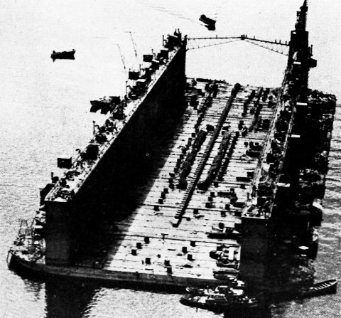
The problem of providing floating drydocks capable of moving to advanced operational areas in the wake of the fleet, of sustaining themselves in full operation without support from shore, and of sufficient size and lifting capacity to dock all capital ships had been under study by the Bureau for many years. The ARD-3 was one solution of this problem. It was recognized that a unit dock of this size possessed certain disadvantages. In required a special basin of huge size for its initial construction. It was necessary to retain this basin Advance Base Sectional Dock
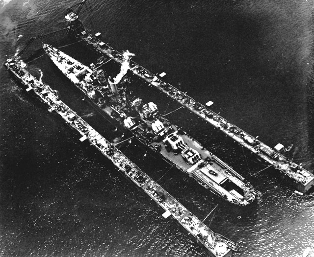
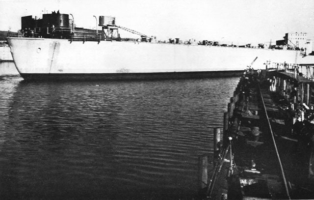
Cruiser in an Advance Base Sectional Dock
Showing the ship secured in position so that it will be supported on the prepared blocking as the dock is unwatered.in reserve or provide an equivalent basin elsewhere, for the periodic docking of the hull, since it was not self-docking. The towing of a craft of this size presented an operational problem of unprecedented magnitude. Provision for stresses during storms at sea required heavy reinforcement of the dock. Concern was felt over the possibility of losing the unit dock from enemy action while en route.
Studies had been carried on concurrently by the Bureau on various types of sectional docks, which would be designed with faired hulls for ease of towing and with joint details which would permit rapid assembly in forward areas under adverse conditions. These schemes were not carried to a final conclusion, primarily because the requirements of the Bureau of Ships for the longitudinal strength and stiffness of the assembled dock could not be met by an practicable form of joint.
When war was declared, it was apparent at once that a number of mobile capital-ship floating drydocks would have to be constructed immediately. The project was authorized and funds made available early in 1942. Studies in connection with the preparation of plans and specifications led to the proposal of a sectional type of dock, with field-welded joints, designed for a strength materially below that previously specified by the Bureau of Ships. This reduction was accepted, and the sectional type adopted.
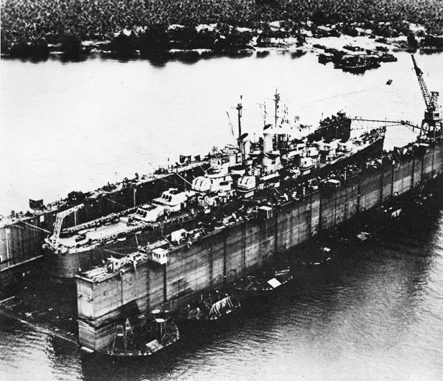
Unwatering an Advance Base Sectional Dock
Water is pumped out of the bottom pontoons and wingwall compartments to raise the ship out of the water.These docks were of two different sizes. For battleships, carriers, and the largest auxiliaries, the larger docks, consisted of ten section, each 256 feet long and 80 feet wide, and with a nominal lifting capacity of 10,000 tons. When assembled to form the dock, these sections were placed transversely with 50-foot outrigger platforms at either end of the assembly, making the dock 927 feet long and 256 feet wide overall, with an effective length of 827 feet, a clear width inside wing walls of 133 feet, and a lifting capacity of 90,000 tons.
The smaller docks, intended for all except the largest battleships, carriers, and auxiliaries, consisted of seven sections, each 240 feet long and 101 feet wide, with a lifting capacity of 8,000 tons. The assembled dock had an effective length of 725 feet, an overall length of 825 feet, a width of 240 feet, a clear width inside wing walls of 120 feet, and a lifting capacity of 55,000 tons.
At maximum submergence the 10-section docks had a depth over the blocks of 46 feet, with a freeboard of almost 6 feet; the 7-section docks had a corresponding depth of 40 feet and and a freeboard of almost 5 feet.
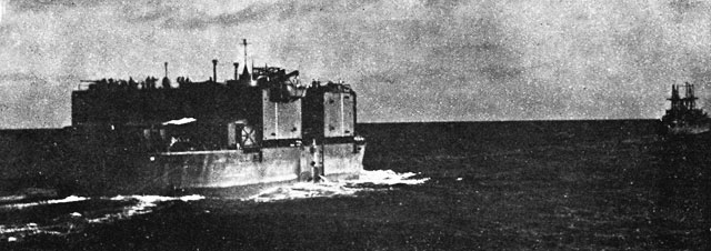
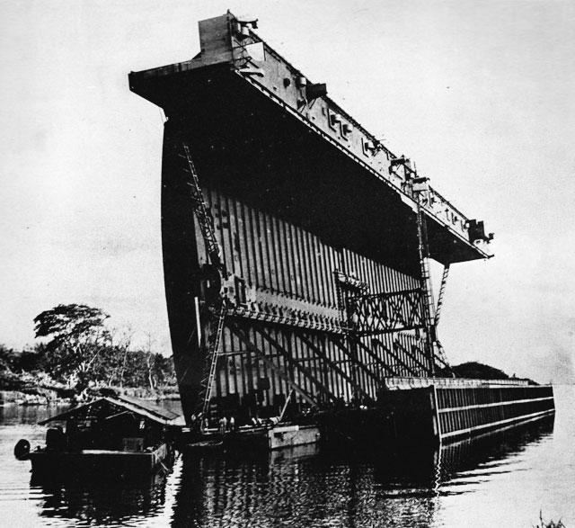
For both sizes, the sections were faired fore and aft to a truncated bow and stern, and could be
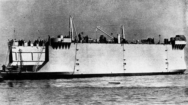
A Section of an Advance Base Sectional Dock in Tow
Wingwalls are down to reduce wind resistance. Repair equipment is stowed on deck.towed at a speed of 6 to 8 knots without excessive power. In the assembled docks, the flat bows and sterns formed interrupted berths alongside to which barges and vessels could be readily moored.
The sections consisted of the bottom pontoon and two wing walls, which were hinged at the bottom so that they could be folded inboard for towing, the purpose being to reduce the presentation to the wind and to lower the center of gravity as compared to fixed standing wing walls.
Each bottom pontoon of the battleship dock was 28 feet deep and was subdivided by two watertight bulkheads running lengthwise and four watertight bulkheads athwart the section to form twelve water ballast compartments and a central buoyancy compartment, 36 feet by 80 feet. This buoyancy compartment contained two decks, the upper deck being used for crew's quarters, and the lower deck, for the machinery compartment. The double bottom was subdivided to form fuel-oil and fresh water tanks. Access to the usable compartments was provided by passageways under the upper pontoon deck which connected to stair trunks in the wing walls.
The wing walls were 20 feet wide and 55 feet high, and were subdivided by a safety deck set 14 feet below the top deck to form dry compartments above and three water ballast compartments below. The dry compartments were completely utilized for shops, storage, and similar facilities. Quarters and galleys were in the dry compartments in the bottom pontoons.
Each section was equipped with two 525-h.p. diesel engines directly connected to 350-k.w. generators, and with pumps evaporators, compressors, and heating and ventilating apparatus. No propulsion machinery was provided.
The smaller docks were similar, except that the bottom pontoons were 231/2 feet deep and the wing walls were 18 feet wide and 49 feet high.
Each dock was equipped with two portal jib cranes having a lifting capacity of 15 tons at a radius of 85 feet, traveling on rails on the top deck of the wing walls. In the case of the smaller dock, the cranes were set back from the inner face of the wing walls to provide clearance for overhanging superstructures of carriers, and the outer rail was supported on steel framing erected on the outboard portion of the pontoon deck.
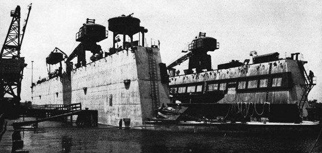
ABSD Construction. -- The 58 sections required for these docks were constructed by five contractors at six different sites, including four on the West Coast, one on the Gulf Coast, and one near Pittsburgh on the Ohio River. Generally, they were built in dry excavated basins which were flooded and opened to the harbor for launching. In one case, two basins in tandem were utilized to suit local site conditions, and the sections were locked down from the upper basin, in which they were built, to the lower basin, the water level of which
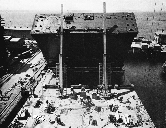
Raising the Wingwalls of an Advance Base Sectional Dock with Hydraulic Jacks
Crews on top of wingwalls change position of the pins in the beams alternatively.was normally at tide level and was raised temporarily by pumping.
At one yard, the sections were built on inclined shipways and end-launched; at another, they were side-launched. These sections were built in from 8 to 14 months. Maximum possible use was made of prefabrication and pre-assembly methods.
ABSD Assembly. -- Although the wing walls were generally erected initially in their upright position for ease of construction, it was necessary to lower them to the horizontal position for towing at sea. On arrival at the advance base where they were to be placed in service, the wing walls were first raised again to their normal position and the sections then aligned and connected.
An ingenious method was evolved for the raising of the wing walls, which was found to be quicker and more certain than the scheme originally contemplated of accomplishing the result by the buoyancy process. Each wing wall was jacked into position, using two jacking assemblies, each consisting of a long telescoping box strut and a 500-ton hydraulic jack. Closely spaced matching holes were provided in the outer and inner boxes of the strut through which pins were inserted to permit holding the load while the jacks were run back after reaching the limit of their travel. These devices were also designed to hold back the weight of the wing walls after they passed the balance point during the raising operation. Two 100-ton jacks opposing the main jacks were used for this purpose. After the wing walls were in
the vertical position, they were bolted to the bottom pontoon around their entire perimeter, and all access connection between the wing wall and bottom pontoon were made watertight.The sections of each dock were successively brought together and aligned by means of the matching pintles and gudgeons which had been provided for the purpose on the meeting faces of the sections. Heavy splice plates were then welded in position from section to section across the joints at the wing walls, at top and bottom, and on both the inside and the outside faces of the wing walls. The strength of these connections gave the assembled dock a resisting moment of about 500,000 foot-tons, or approximately one-fourth that of the largest prospective vessel to be docked.
The drydock cranes were carried on the pontoon deck of individual sections during tow, and were shifted to their operating position on the wing walls during assembly of the dock by immerging the partially assembled dock, bringing the section carrying the crane alongside, and aligning it so the rails on the pontoon deck were in line with those on the wing walls of the rest of the dock. The trim and alignment were adjusted during the transfer by a delicate control of water ballast.
The assembled docks were moored at anchorages in protected harbors where wave conditions, depth of water, and bottom holding power were satisfactory. The large docks required at least 80 feet depth for effective use. They were moored by 32 fifteen-ton anchors, 14 on either side and 2 at either end, with 150 fathoms scope of chain.
In actual operation, it was found that the effectiveness of these docks could be improved by providing auxiliary facilities in excess of those available on the dock itself. A considerable number of shop, storage, and personnel accommodation barges were provided for this purpose.
The largest single group of floating drydocks built during the war was the auxiliary repair group, or ARD's. Designed to accommodate destroyers, submarines, and other craft of comparable limiting dimensions, these docks were extensively used throughout the combat areas and proved among the most useful, flexible, and effective facilities supporting the combat fleet. Auxiliary Repair Dock
The early history of the development of this class has been recounted earlier in this chapter. The pre-war ARD-1, completed in 1934, was in operation at Pearl Harbor and demonstrating its effectiveness when the developing emergency dictated the provision of additional docks of this type. The ARD-2 and the ARD-5, undertaken in 1940, with slight modifications in size, from plans and specifications prepared several years earlier by the Bureau, incorporated many improvements and refinements indicated as desirable by the experiments conducted on the ARD-1.
These docks were 485 feet 8 inches long and 71 feet wide overall, and had a usable length of 413 feet, a clear width of 49 feet 4 inches, and a depth over the blocks of 21 feet, providing a nominal lifting capacity of 3,500 tons. They could, however, lift a much heavier ship if its weight distribution were favorable. The hull was designed and built as an integral unit structure, and was strong enough to resist safely the maximum hogging, sagging, and torsional stresses to which the dock might be subjected in heavy storms at sea. These provisions for sea stresses made the ARD docks exceptionally rigid when in normal use.
These docks were well compartmented, both for maximum safety at sea or in combat and for optimum control of ballasting during docking operations. The bottom pontoon was divided by one longitudinal and four transverse bulkheads into eight ballast tanks. Each wing wall was divided into five ballast tanks, and, in addition, two tanks were provided in the bow, forward of the head wall of the inner dock. A watertight horizontal safety deck installed in the wing walls and bow precluded immergence below the minimum designed freeboard and helped to prevent undue trim or list at deep draft.
These ballast tanks were interconnected by valved piping to two pumping plants, each consisting of two vertical shaft pumps rated at 15,000 g.p.m. at 12 feet head. The flooding and pumping system permitted submerging the dock to minimum freeboard in 50 minutes, and raising the dock and pumping the basin dry in 100 minutes. The ballast tanks were equipped with water-level indicators centralized in the control house, from which all pump and valve operations were also remotely controlled.
Above the safety deck in the wing walls were two machinery decks. The lower, or C, deck accommodated the pump and valve motors, small machines, welding equipment, and storage spaces. The upper, or B, deck accommodated the main
diesel generators and other heavy equipment, as well as quarters and messing facilities for the crew. In the bow, the upper deck was omitted in order to provide adequate headroom for the hull repair shop.These docks were equipped with four railway-type diesel engines directly connected to electric generators. As originally designed, provision was made in these docks for the installation of low-power electric-drive propulsion machinery. None of the docks was actually equipped with propulsion, partly because of the urgent need for such equipment for ships and partly because of the infrequent use which could be made of it.
These docks were provided with bottom-hinged stern gates of a type different appreciably from the gate used for the ARD-1. They were closed by an electrically driven sprocket and roller chain device at either side, and opened by gravity. Operating difficulties with this mechanism led eventually to its replacement with hydraulic gate operating gear similar to that used in the ARD-1 and providing positive force and control for both closing and opening.
In addition to the ARD-2 and the ARD-5, six other docks of the same dimensions were construction in 1942 and 1943. The rapid production of landing craft undertaken in 1942 dictated provision
ARD-13
Showing completed dock basin with keel-bilge rails and blocking timbers, deck stairs and railing with cat walk, two 10-ton jib cranes.
View looking forward from the flying bridge of the ARD-13.
ARD-14
Photograph taken during the launching of the dock, November 6, 1943.of mobile drydocks capable of handling the LST's, which were of greater beam than the clear width between the wing walls of the ARD's under construction. All subsequent docks of this class were built to revised designs providing a clear width of 59 feet between the wing walls.
These docks proved to have excellent towing characteristics. Many trans-Pacific movements were made at average speeds of 6 to 8 knots, using fleet tugs and auxiliaries of moderate horsepower. The particular advantage of these docks was their readiness for immediate service as soon as they were moored.
The need for more auxiliary facilities than could be accommodated on board the docks led to the provision of a covered wooden barge equipped as a carpenter shop for each dock. Keel blocks, cradles, and shoring timbers needed for docking or repairs were fabricated on this shop barge, which was moored alongside the drydock and supplied with power from it.
A vast number of combat vessels damaged in action or requiring graving of the bottom or other hull work below waterline were successfully docked in ARD's in the forward areas. This service to the fleet constituted a significant factor in the success of the Navy, particularly in the later actions in the western Pacific.
In 1943, the indicated requirement for a number of additional drydocks, coupled with the critical shortage of steel plate and the necessity for allocating the available supply to other programs, led the Bureau to undertake the design and construction of thirteen 2,800-ton reinforced-concrete docks, designated as ARDC's. Auxiliary Repair Docks, Concrete
The Bureau had previously designed and built
Auxiliary Repair Dock, Concrete
Photograph taken at Wilmington, N.S.two small concrete floating drydocks of the YFD class, of 400 tons capacity, and had thus gained considerable experience and specialized information on the problems involved.
The ARDC's were monolithic structures of the open trough type, with faired hull lines at the bow and stern. They were 389 feet long, 84 feet wide, and 40 feet deep overall, with pontoons 14 feet deep and wing walls tapering from 13.5 feet at their base to 10 feet at the top deck.
The bottom pontoon was subdivided into twelve compartments by a longitudinal center-line bulkhead and five transverse bulkheads, the midship one being made double to provide a dry passage across the dock.
The main structural elements of the pontoon were rigid transverse frames, 6 feet on centers, with members 8 inches thick and 20 to 30 inches deep, and heavily reinforced to resist the transverse stresses incident to ship loading concentrated on the center keel blocks. Longitudinal stresses were resisted by the watertight bulkhead on the center line, by the non-watertight bulkheads directly below the inside face of each wing wall, and by the side shell. The bulkheads were 6 inches thick, and the bottom side and deck slabs were 53/4 inches thick. The wing-wall frames were also 6 feet on centers with 8-by-16-inch and 12-by-20-inch members and with slabs 51/2 inches thick.
Six of these docks were militarized and equipped with three diesel engines each, directly connected to 200-kw alternating-current generators for the main electric power supply. These docks were also provided with air compressors, refrigerating, heating, and ventilating equipment, and with water evaporators. They carried a crew of five officers and 84 men. The other seven docks of this class were not fully self-contained and required power supply from shore.
A diesel- or diesel-electric-powered traveling job crane, having a lifting capacity of 5 tons at 42 feet reach, was provided on top of each wing wall.
ARDC Construction. -- Eight of these docks were built on the East Coast, at Wilmington, N.C., and five of the West Coast, at San Pedro, Calif., in dry basins excavated for the purpose. Pile-supported platforms were constructed on which the hulls were built. Forms were of wood and masonite, and were held to close tolerances to avoid wide inaccuracies in fin displacement. Concrete was composed of stone or gravel aggregate, with about 8.4 bags of cement per yard and a water-cement ratio of five gallons per bag of cement to secure maximum density and a 28-day strength of more than
AFD-10, a 1,000-ton Lifting Capacity, Steel Dock4,000 pounds per square inch. A total of 3,300 cubic yards of concrete was required for each dock.
ARDC Service. -- Five of the self-contained docks of this class were towed to advance bases in the Pacific or to Pearl Harbor, where they were utilized with great success in the repair of many combat-damaged vessels. In service, these drydocks proved unexpectedly popular, because of their relatively great mass compared with their lifting capacity. This characteristic lowered the center of gravity and also made the dock exceptionally stable. It was not necessary to admit water into the wing walls to sink the docks, and additional space for machinery and quarters was thus made available. These docks also proved exceptionally watertight and required practically no hull maintenance.
Another large class of docks were the 1,000-ton one-piece steel docks designed by the Bureau, intended for docking minesweepers, patrol craft, and similar vessels, and designated as AFD's. Auxiliary Floating Dock
These docks were of the trough type, 200 feet long and 64 feet wide, with a clear width inside the wing walls of 45 feet, and a draft over the blocks of 141/2 feet. They were entirely of welded steel construction. They were fully self-contained, with diesel electric power plants, and contained limited repair facilities.
Construction of these docks was distributed among five contractors, using six different plants, of which three were on the East Coast, one on the Gulf Coast, one on the West Coast, and one on the upper Mississippi.
These docks proved extremely trim, handy, and efficient. They served a great variety of smaller vessels, of which great numbers were required by the multitudinous demands of global war, and while the service was perhaps not as spectacular as that of the ABSD's and ARD's, they contributed materially to vital phases of the fleet's activity.
When the escort-destroyer program was initiated, it was apparent that additional drydocking facilities would be required for the repair and overhaul of this large group of combat vessels. The DE's were too long and too heavy to permit their docking in the AFD's, although their beam and draft were within the clearance limits of these docks. Auxiliary Floating Dock, Lengthened
First Ships in YFD-16 Jacksonville, February 1943
Most YFDS's were maintained tied up to a wharf or bulkhead, fitted into a notch that would allow vertical movement but would keep the dock in position.Five of the AFD's were modified by adding an 88-foot section amidships, increasing their overall length to 288 feet and their lifting capacity to 1,900 tons. these docks were also fully self-contained.
In addition to the military requirements for a great fleet of mobile, self-contained floating drydocks docks designed to render direct close-up support of the combat Navy, there were innumerable demands for many types of floating drydocks of the yard or harbor variety, both in this country and by our Allies. Many merchant vessels were being torpedoed by submarines or damaged by mines. Although some of these ships were sunk, there were many which succeeded in reaching port, and the necessity for their prompt repair threw an overwhelming load on the naval and commercial yards. Moreover, the anti-submarine campaign necessitated a vast augmentation of the Atlantic Fleet, with a great many different types of combat and patrol vessels and craft; the long-range Pacific naval war similarly overburdened the relatively limited West Coast yards. The British were also Yard Floating Dock
desperately short of drydocks in all theatres of action.To overcome this critical deficiency, a major program of YFD's was undertaken in 1941 and continued aggressively through 1942, 1943, and 1944. In all, 66 docks of this designation, varying from 20,000 tons to 400 tons lifting capacity, were constructed, and two were purchased.
Sectional timber docks. -- Several of these YFD's were large commercial-type sectional timber floating drydocks. Some were contracted for under Bureau of Yards and Docks contract; others, under Bureau of Ships facilities contracts. They were designed by engineering firms and built by a number of contractors, at various locations, under the supervision of the Bureau. In general, they were equipped with relatively simple pumping plants and were dependent on shore connections for their power supply.
The largest were of 20,000-ton lifting capacity, were 659 feet long and 1321/2 feet wide overall, with a clear width of 97 feet and a maximum depth over the blocks of 25 feet 8 inches. They were composed of six sections, with locking devices capable of holding the sections together and in alignment.
Other sectional timber docks were built with capacities of 16,000 tons, 12,000 tons, 10,500 tons, and 7,000 tons. The 16,000-ton docks were identical with the 20,000-ton docks, except that five sections were used, and the overall length was reduced to 559 feet. The 12,000-ton docks were of a different design, with sections joined in such a way as to transmit some shear and bending; the 10,500-ton and 7,000-ton docks were identical in all dimensions except length, six sections being sued for the former and four for the latter.
Three-piece steel docks. -- The YFD program included the design and construction of a number of large steel drydocks built in three sections to permit self-docking. These docks had a long center section and two short end sections, which could left the center section or could be turned 90 degrees and docked on the center section for repairs. In principle, these docks were modern counterparts of the old Dewey Dock, but many improvements in design and equipment were incorporated. Although these docks were intended primarily for use where yard facilities were available, a number of them were equipped with diesel-driven electric generators and were, for all practical purposes, self-sustaining.
These docks were built in three sizes and capacities. The 18,000-ton docks were 622 feet long and 124 feet wide overall, with a clear width of 94 feet and a depth over the blocks varying from 28 to 31 feet. The 15,000-ton docks were 615 feet long and 116 feet wide overall, with a clear width of 871/2 feet and a depth over the blocks of 30 feet. The 14,000-ton docks were 598 feet long and 118 feet wide overall, and provided a clear width of 87 feet and a depth over the blocks of 28 feet. Designs were also prepared for a 12,000-ton dock of this type, but none was built.
The three-piece docks were built at a number of sites on the Atlantic, Gulf, and Pacific coasts. Generally, the sections were constructed on inclined ways and side-launched. Welded construction was used exclusively for fabrication and assembly, except that the three sections are joined by closely spaced bolts.
Some of these docks were placed in service at commercial repair yards, and a few were utilized overseas by the Navy, to supplement its auxiliary drydock fleet.
One of the most interesting operations in connection with these docks was the transfer of two docks, the YFD-3 and the YFD-6, from the Atlantic to Balboa, on the Pacific side of the Panama Canal. This transfer was necessary to increase docking facilities on the Pacific side of the Canal, and to make it unnecessary for tankers to transit the canal for repairs.
Since the center section of these docks was wider than the clear width of the locks, it was necessary to adopt special measures for their transit. A scheme was developed for towing these sections through the canal on their beam ends. One thousand Navy pontoons were installed on one wing wall; the latter, reinforced with struts; and the dock section, rotated 90 degrees by a carefully precalculated progressive flooding and pumping operation. After transit, the sections were righted and the docks reassembled.
One-piece timber docks. -- To augment the number of small docks without undue drain on the limited supply of steel plate, the Bureau designed a one-piece timber dock of 1,000-ton lifting capacity and procured 25 of them through contracts with various builders on both coasts. These docks were of the trough type. The hull was 200 feet
YFD-6 Being Prepared for Passage Through the Panama Canallong and 64 feet beam. Outriggers increased the overall length to 240 feet. These docks had a clear width of 48 feet and a maximum depth over the blocks of 14 feet. They were particularly useful for overhaul of patrol craft and were widely distributed, particularly at the bases in the Atlantic and Caribbean. One dock was constructed at an overseas base. Two additional docks were enlarged to provide 1,800 tons lifting capacity.
A few one-piece timber docks of larger size were constructed for repair yard use. The were of 3,000-ton, 3,500-ton, and 5,000-ton lifting capacity. The latter were 412 feet long, 90 feet wide, and provided a clear width of 64 feet and a maximum depth over the blocks of 19 feet 4 inches.
The Bureau also provided a number of docks of special types and varying capacity for specific objectives. Special Docks
The largest of these docks was a Rennie type dock, consisting of steel wing walls beneath which seven timber pontoons were independently bolted. The pontoons were each 77 feet wide and 120 feet
YFD-6 Careened at an 85-degree Angle for Passage Through the Panama Canallong and provided a total lifting capacity of 16,000 tons. Self-docking was accomplished by withdrawing one pontoon at a time and docking it on the remaining units.
Another unusual type was the 400-ton concrete dock designed by the Bureau for use in repairing small patrol craft. The success of these docks for this purpose was a factor in the adoption of concrete for the ARDC's.
The 155 floating drydocks constructed and purchased under this intensive building program were deployed throughout the world, and used by many agencies. A total of 78 docks saw service in advance areas. Commercial ship repair yards utilized 44, and continental naval activities, 21 docks. Three docks were furnished to Army ports of embarkation, two docks to the Coast Guard, and five to the United Kingdom; one was lost, and one was sunk in the Bikini tests. Deployment
A major problem in the provision of overseas docking facilities was the task of getting these docks safely to their destinations. This required
Training Center at Paradise Cove, Tiburon, Calif.
Here men were trained to operate floating drydocks.careful study of the various factors involved and the provision on the docks of abundant tackle and protective devices, to insure the safety of the docks and their crews so far as this was humanly possible. This work included, an many cases, the development of plans for the safety of floating and other structures which it was necessary to transport to advance base areas in or on the docks. The ARD docks, in particular, were fine freight carriers and seldom left for their overseas bases with an empty center chamber. On the contrary, they usually carried their own work barges, small boats, dredges, cranes, locomotives, piling, and other supplies too numerous to mention. Standard towing and stowage plans were developed and rigorously followed for all these conditions of service. As a result, the losses in these vast towing operations were practically negligible even through much of the towing was done in enemy-infested waters and double, triple, and even quadruple tows were necessary at times due to shortages of tugs and tug crews.
Simultaneously with the construction of the Navy's floating drydocks, it was necessary to plan for providing trained personnel to operate the docks. A training center was established on Tiburon Peninsula on the shores of San Francisco Bay, not far from the town of Tiburon. Floating Drydock Training Center, Tiburon
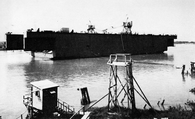
Work on the facility was begun November 19, 1942, under a CPFF contract, which called for barracks, subsistence and administration buildings, a ship pier, and utility services. The work was usably complete by January 15, although barracks
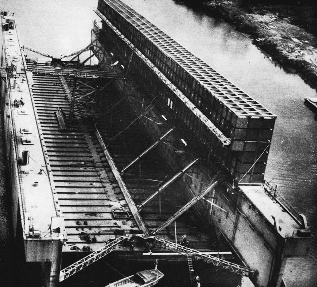
Launching the Center Section of YFD-6
This 18,000-ton steel floating drydock was launched at Morgan City, La., October 1943.and buildings were occupied before the steam heating plant had been completed, the deficiency being met by obtaining steam for heating purposes from the USS Crockett, which was moored at the pier.
This activity was in charge of an officer who had had considerable experience in advance base floating drydock work. Under his guidance, several thousand officers and men were trained in time to play a prominent part of the great overseas ship-repair activity.
Special conditions of service involved many entirely new studies and developments for our floating drydocks. For instance, as the docks had to operate in outlying areas where ideal conditions for operation could not always be met, it was necessary to give the adequacy of their moorings special consideration. In the largest size docks, this involved wind-tunnel experiments which gave some surprising results and indicated that a rearrangement of the moorings as originally planned was desirable. Also, as the drydock operating crews were initially relatively inexperienced and docking of ships under advance base conditions had never been attempted to the extent contemplated, it was necessary to prepare complete operating manuals for the use and guidance of the crews. Damage control was also important, and damage-control manuals were prepared for all advance base docks, covering every possible contingency of weather an enemy action. Special Problems
As advance base docks were commissioned and had regular Navy crews and as they operated in areas where they had to be self-sustaining to a large extent, it was necessary to develop allowance lists for each type of dock and outfit them in much the same manner as a ship. This necessitated the incorporation into the docks of special facilities for the handling, stowage, and issuance of great quantities of material and equipment.
Complete statistics have not been compiled of the total number of vessels of all kinds from the mightiest battleship and carriers to the humblest patrol craft that were salvaged, repaired, and overhauled in this armada of floating drydocks. The
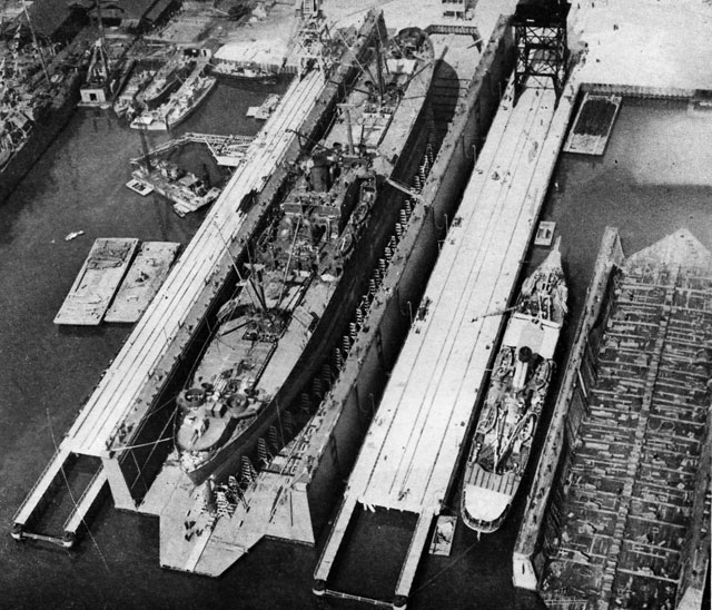
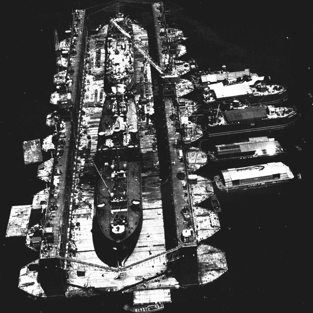
Ten-Section ABSD (Advance Base Sectional Dock) in Service
Two ships received simultaneous service in a dock capable of servicing the largest vessel afloat.
The small barges moored to the side are additional service units.most dramatic demonstration of the importance of the mobile drydocks was given during the long drawn-out naval support of the invasion of Okinawa, when the fleet was subjected for weeks to continual and desperate "Kamikaze" attacks by Japanese suicide-bombers. The fleet suffered great damage, but the ready availability of the mobile drydocks at nearby advance bases, and the yeoman service rendered by their own crews and the ship repair components at these bases, save many ships and minimized the time ships were out of action for repairs, to such an extent that these docks may well have represented the margin between success and failure.
Table of Contents
Previous Chapter (8) * Next Chapter (10)